Important Safety Notes: |
A minimum of two people should always be employed to lift a Uniware guest card terminal. A third or fourth person must be employed in order to mount the unit. Ensure that you follow your on-site health and safety procedures, and identify any risks to the relevant parties. |
Length: 760mm
Width: 260mm
Depth: 350mm
Weight: 50kg when full.
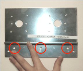
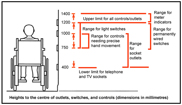
1. The terminal comes with a mounting bracket that incorporates three 6mm holes (fig. 1). These holes match three holes on the rear of the terminal itself. You must mark these three holes at the required height on the wall onto which the terminal is to be mounted (see fig. 2: DDA guidelines).

fig.1

fig. 2 DDA guidelines
2. Drill out the three holes that have been marked on the wall, fill them with rawplugs (supplied???), then fix the bracket to the wall with two ......mm screws (supplied???) in the outer holes only.
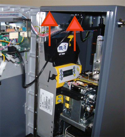
3. Before mounting the terminal onto the wall bracket, its internal coin mechanism must be removed. This will allow access to the inside rear of the terminal in order to fix it to the wall bracket. Remove the coin mechanism by opening the terminal door, and lifting the mechanism up and away from its mount (fig 3). You will then need to disconnect its molex plug.

fig.3
4. You are now ready to fix the terminal to its wall bracket. Before doing so, however, note the following two points:
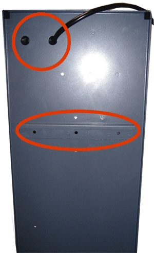
a) There are two 15mm holes in the top rear wall of the terminal to accommodate the (supplied???) power and ethernet cables (fig. 4). These cables should be fed through before the terminal is mounted onto its wall bracket (alternatively there is a cable ridge at the top of the terminal where you can also run the two cables).
Note: |
Ensure that you leave enough slack on the ethernet cable to accommodate opening the terminal door. |
b) The terminal rear wall also includes three holes that line up with the wall bracket. Just above these holes is a lip which is used to rest the terminal onto the wall bracket (fig 4).

fig.4
5. Lift the terminal and rest its lip over the secured wall bracket.
6. Line up the three fixing holes on the rear wall of the terminal with those on the wall bracket.
7. From the inside, screw a ......mm screw (supplied???) through both the rear wall and the wall bracket, into the wall itself.
8. Re fit and plug in the terminal's coin mechanism.
Note: |
There are two ...mm drilled holes in the base of the terminal if you wish to fix it to a base unit. If this is required, and your guest card terminal includes an optional note reader mechanism, both it and the note reader chassis will need to be removed to access these holes. Remove the note reader and vault first. To remove the chassis unscrew its the 7mm fixing nut. You will then be able to lift it up and out. |